Building Our Dyno Room
I've had the opportunity to work in quite a few dyno rooms during my life. Some were a pleasure to work in, and some were just plain awful. When I decided to build the one for current "hobby shop", there were a number of things that were necessities.
2. Accuracy. The room’s design and construction, along with it’s ducting had to provide a repeatable environment for all testing.
3. Noise. The room had to be quiet, so people on the outside could talk without raising their voices during tests, and while the shop’s situated in an area that’s primarily industrial, I didn’t want complaints over noise if we were running tests at 3AM.
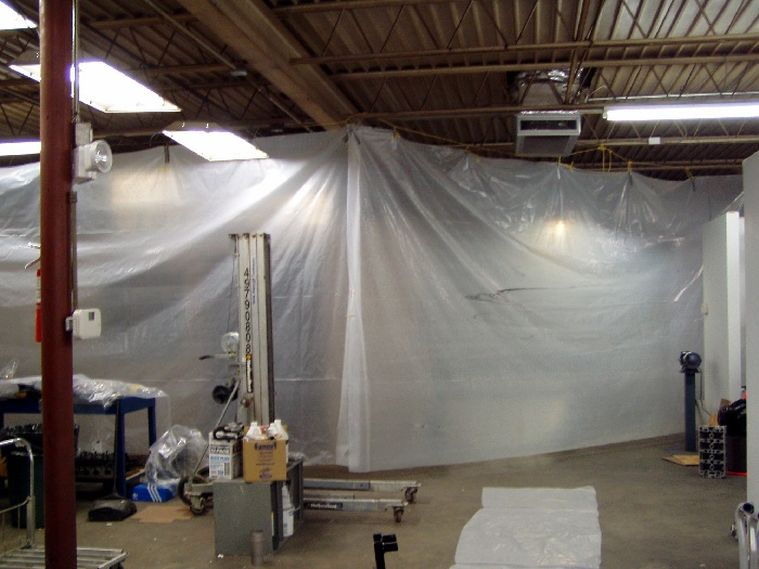
Before beginning the construction process, I strung nylon cable through the roof trusses around the area where the room was going to be located. Using short loops of nylon for sliding connectors, I hung large sheets of plastic to segregate the construction area from the rest of the facility to hold dust-contamination to a minimum. I spent a couple weekends cutting concrete, and jack-hammering the trench for the water drain. Since I was connecting to an existing drain pipe, the trench for the pipe had to have the correct slope over it's 18 foot length for proper drainage. I put a drain for water in the center of the room’s floor (as recommended by Superflow).
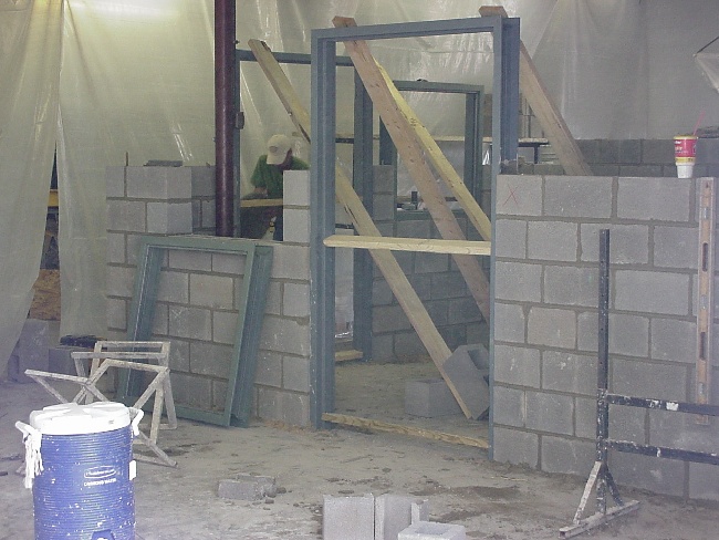
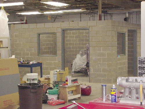
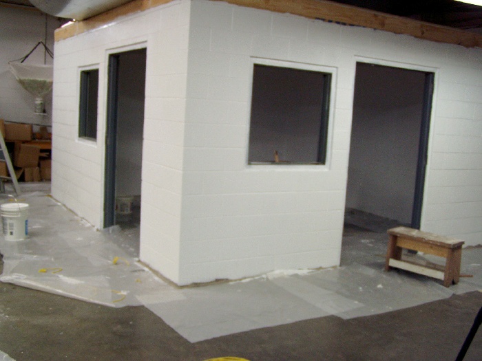
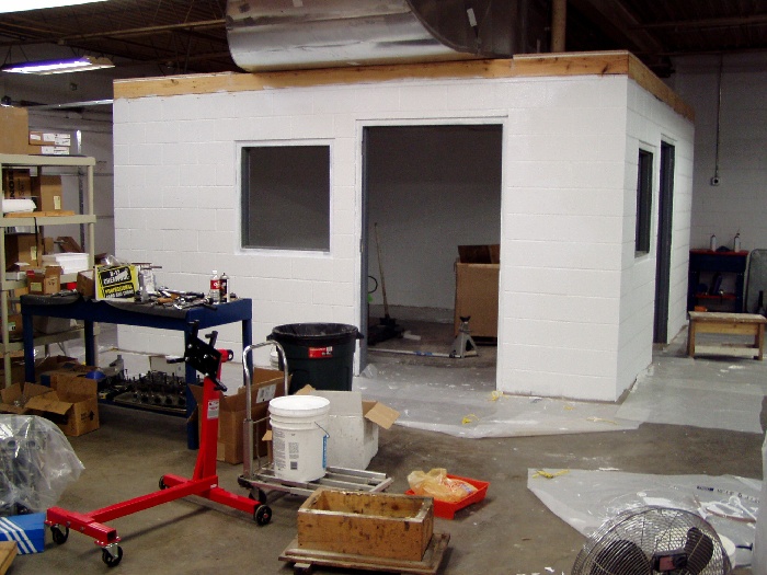
The heavy steel door and window frames were installed during the construction of the walls, so they are an integral part of the structure. The walls are connected to the shop’s concrete floor with reinforced steel rods positioned every 2 feet and in each corner of the structure. The walls were also filled with concrete during construction, effectively making them (solid), and lugs were inserted every 8" at the tops of the walls for ceiling attachment. Note that we had to include one of the building's roof support pipes in one corner of the room.
This is where room construction ground to a halt because the City of Fort Worth determined that I needed to raise the entire building to meet 2003 building codes during this project. Some of the things they required included increasing the building’s parking space from 5 to 8 spaces, including an additional handicapped space. The fact that many buildings on the street had no parking areas other than the street, and that there was no space on the lot for the larger parking lot made no difference. They actually wanted me to teardown the front of the third of the building to build the parking lot! It took an entire year and a couple speeches in City Council meetings to finally beat the city planning office into submission. I did end up rebuilding one restroom to meet handicap specifications, which has ended up being a good deal, especially for wheelchair-bound Mike Garvie (our head and manifold fabricator). At any rate all the wrangling consumed 12 months, and it left me with a much greater understanding of how to deal with the city in the future......
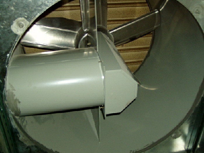
Good ventilation is a must for a dyno room. To serve that purpose, I bought an axial-flow fan and motor combination that moves 28,000cfm through this size room.
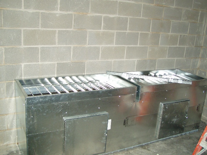
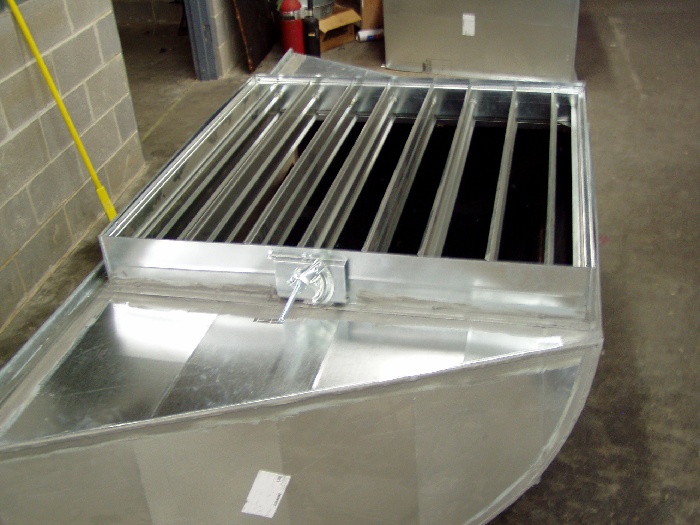
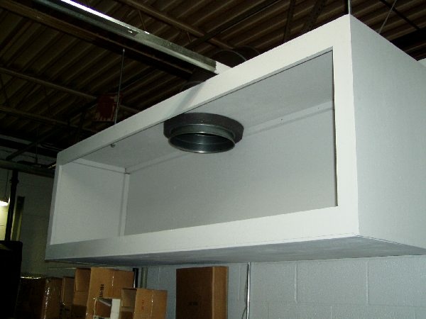
Here's the inlet ducting I designed. We had a sheet metal shop just down the street fabricate all the ducting pieces. The duct is upside-down in this picture. The "squares" are access doors which allow one to crawl into the ducting from the dyno room roof should any maintenance be required. Once again, thinking ahead can make life easier down the road, should there be any problems.
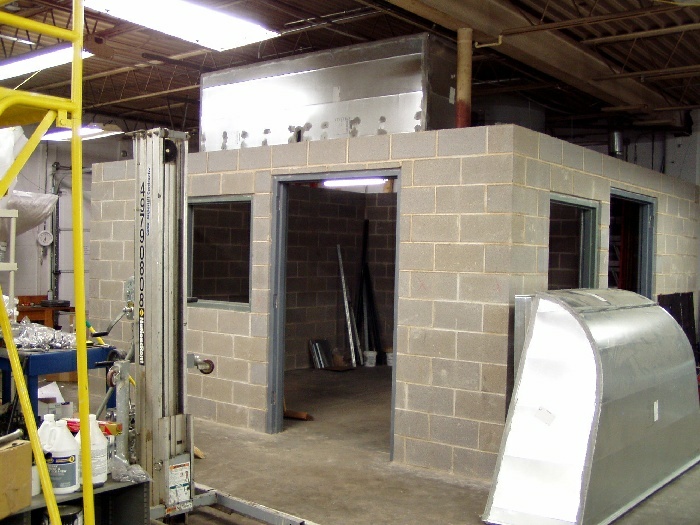
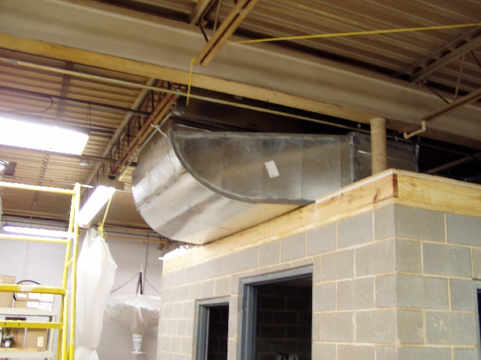
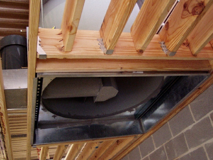
Here's the inlet duct hung in place. The front of the duct will be cut out just before we fit the sheet metal "elbow" (standing beside the room on the floor) that connects to the roof plenum.
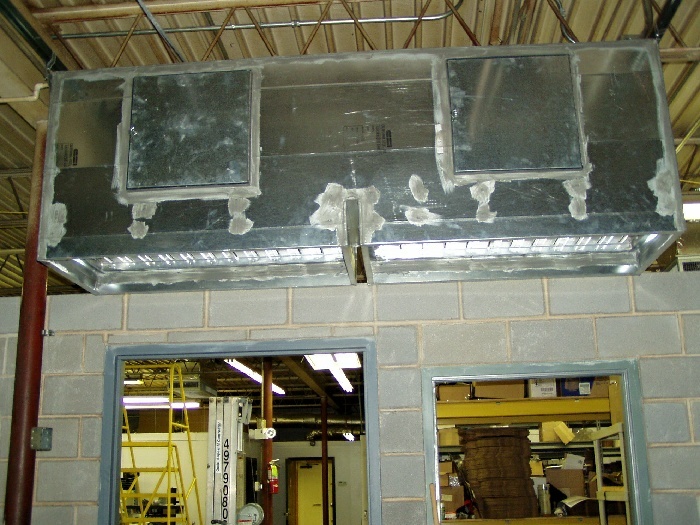
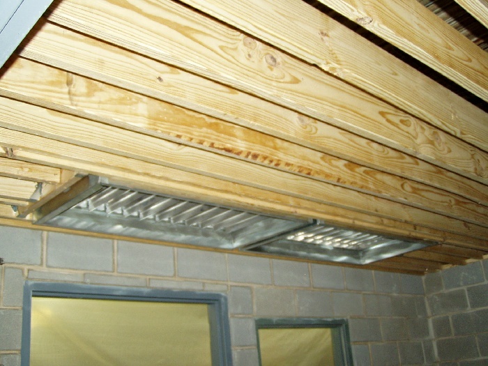
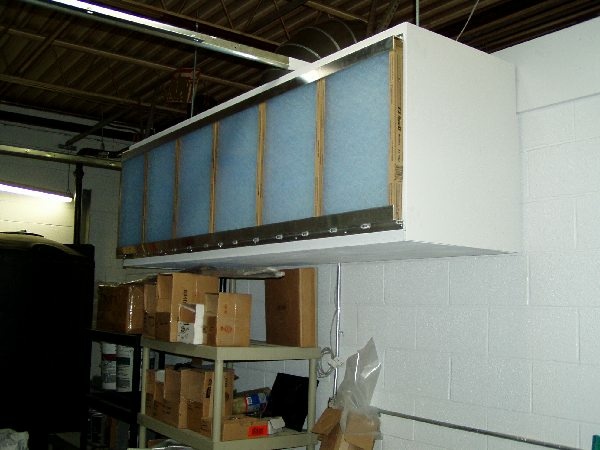
View of the inlet ducting from inside the room structure.
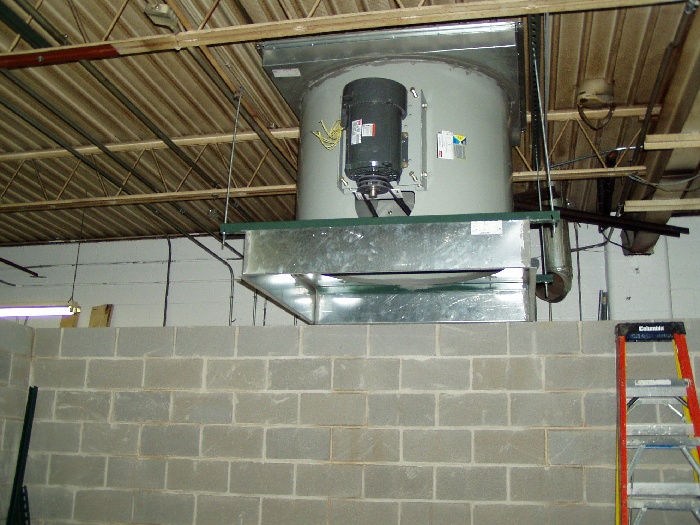
A picture of the outlet with the axial-flow fan hanging in position. I elected to hang almost all of the ducting in it's proper position and height before constructing the room roof structure, so all the sheet metal work could be properly done without the roof being in the way.
Here's a close-up of the inlet "elbow" that connects the room's inlet ducting to the roof-mounted air filter plenum.
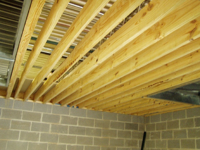
As you can see, we waited until the roof structure was complete before attaching it to the inlet ducting. With the fan and ducting positioned, we were able to build the ceiling structure. The beams are 2” x 7” (yes, I screwed up on the engineering, so we had to cut all of the 2x8"s down to 2" x 7")and they’re spaced every 8”. They’re also “stepped” (per Superflow’s suggestions), so the ceiling inside the room isn’t touching the same studs as the ceiling on the top of the room. The inner ceiling is 2 layers of ¾” fireproof sheetrock and the outer is 2 sheets of ¾” plywood. Sound-deadening insulation is also packed between the two surfaces.
A lot lumber...and a whole lotta sawdust from cutting it.
This construction sequence allow us to surround and mechanically link all the ducting for additional support. Surprisingly enough all the edges of the ducts were actually exactly where they needed to be once we'd installed the sheetrock, making all the grills fit perfectly flush with the inner ceiling.
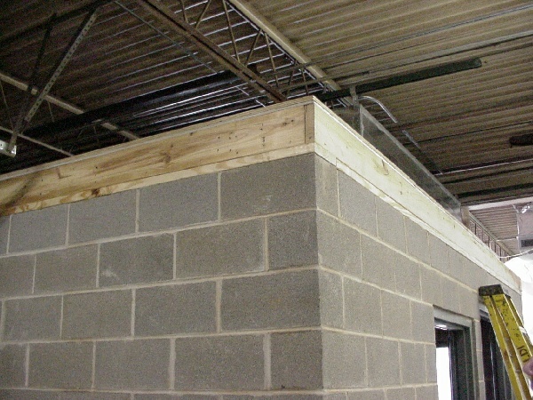
Outer roof structure.
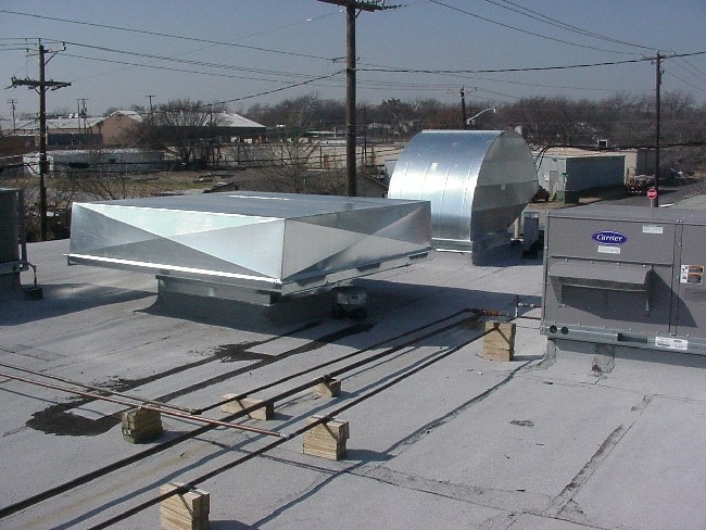
This view shows the relationship between the dyno room's outside ducting and two of the Carrier roof-mounted heating and cooling units.
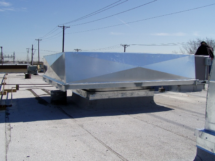
The roof-mounted inlet plenum is low-profile (it's windy here in Texas), and it houses a total of (24) 24"x24" flat air filters. Two of the lower side panels are hinged making sliding air filters in and out an easy job.

The air exit is extremely large and configured to keep moisture "out".
Ahhh.....the wonderful job of sheet rocking, texturing, and painting.....
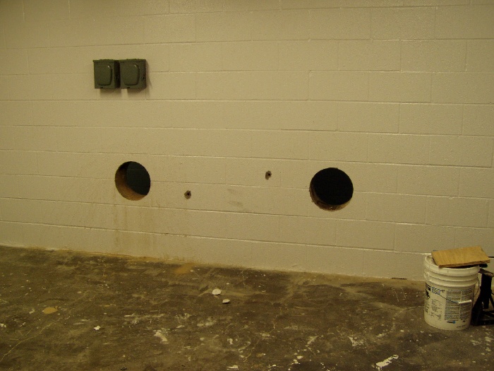
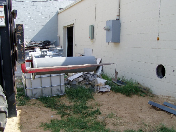
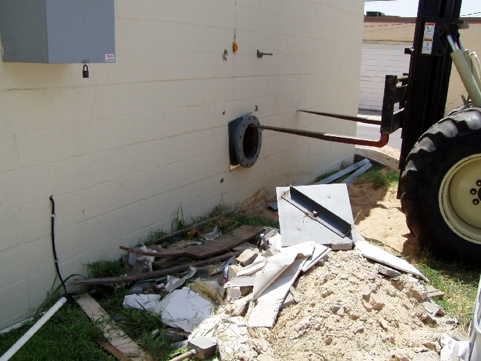
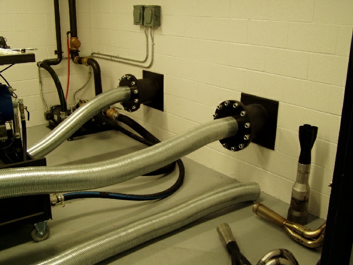
We used a concrete hole saw and a LOT of water cutting the exhaust manifold holes in the wall. We also cut a hole in the front of the room at floor level for routing the dyno and engine ECU wiring once we reach that point in the project.
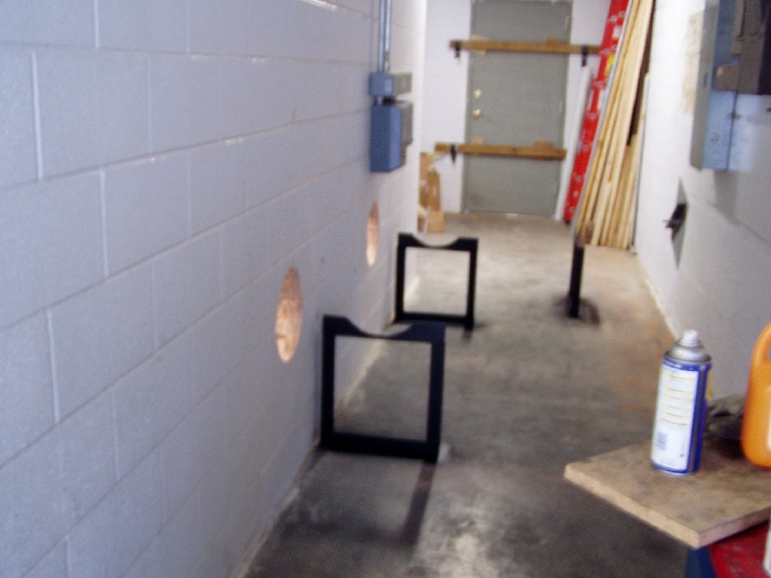
With the exhaust manifolding constructed of 3/4" thick pipe, we fabbed these two supports so the dyno room walls wouldn't be bearing any of the pipe weight.
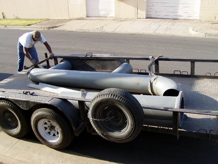
We subbed out the fabrication of the manifolding to another company that's just a couple blocks away from us.
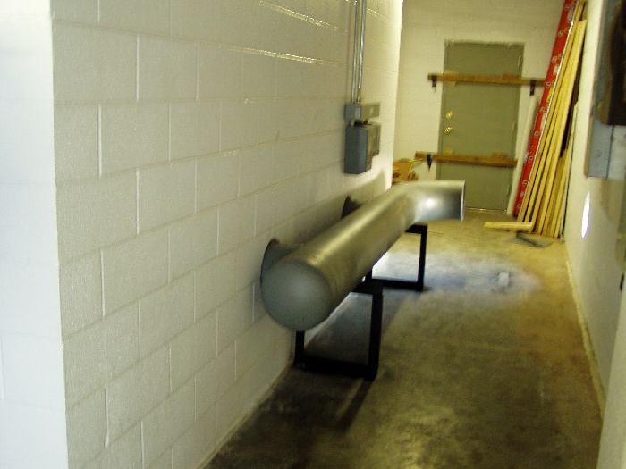
It took a LOT of bodies to lift this section of the manifolding to it's place atop the supports we built.
Here's the pipe that connects the inside manifolding to the muffler. Yes, it's heavy.....
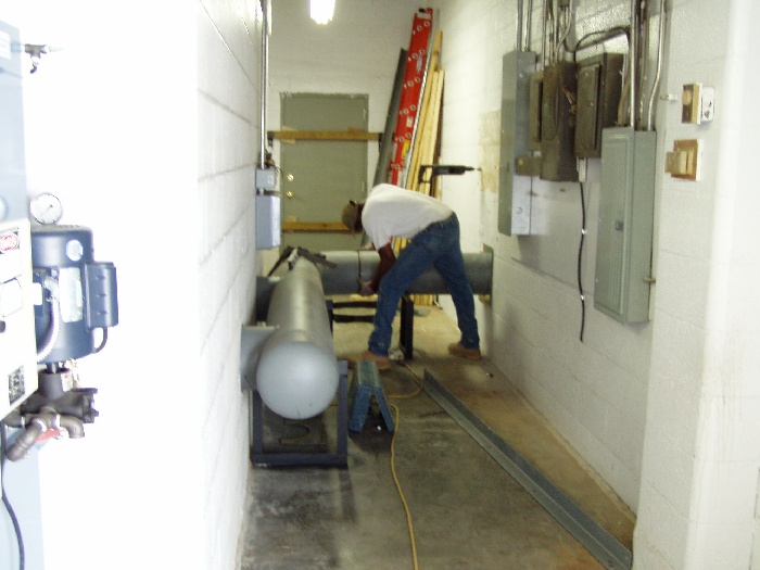
It took a lot of large welding rods to connect these two pieces.
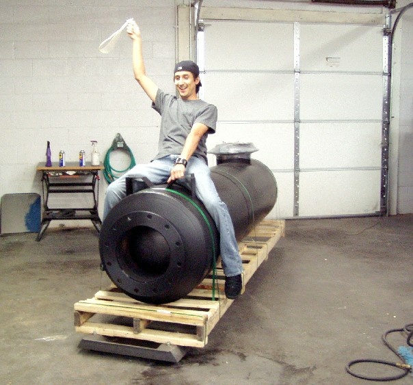
Our hospital-grade 2000hp industrial silencer taking one of our good friends for a ride. Bulls and bucking machines are big here in Cow-town.
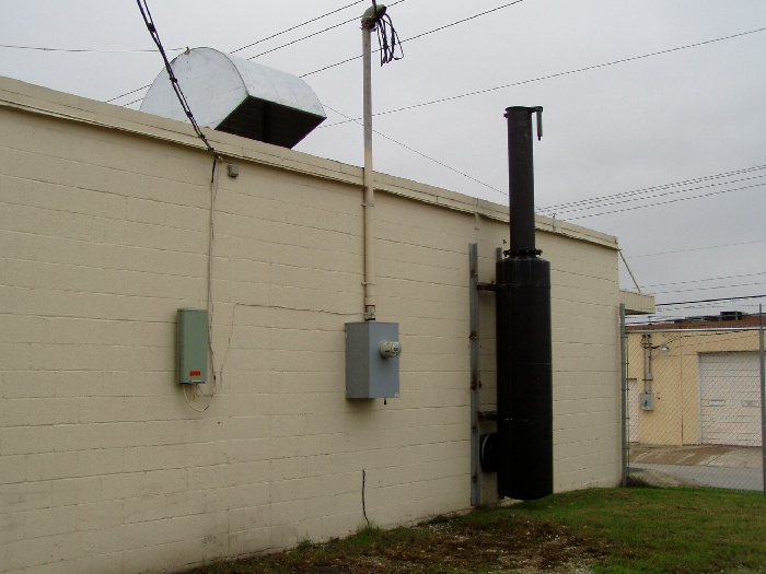
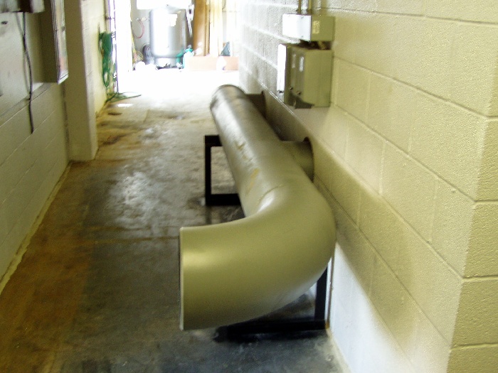
Muffler mounted to the exhaust manifolding and hung from the building. We weighted the cap so it takes very little exhaust flow to push it open.
As you can see in these pics, we've already epoxied the floor. The floor of the building had been oil-soaked by the machine shop that occupied the building for 20 years before I moved in, so we used approximately 10 times the amount of concrete etching acid to properly prep the floor surface before applying the epoxy and to-date we've had no hint of the epoxy coming up. Make sure you have lots of ventilation when you're etching concrete...the fumes are a killer!
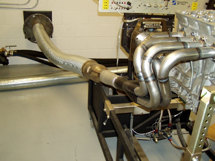
Although I built this place to primarily serve small displacement engines I configured the exhaust system so we could run engines that had headers exiting on either side, as well as combinations (like V8’s) with pipes on both sides. The manifolding that carries the exhaust through the dyno room walls and outside the building is 12” steel pipe with a wall thickness of ¾”…so it’s heavy duty. I did this for both durability and sound considerations. We flanged the pipes that enter the dyno room so we can adapt any variety of exhaust configurations very readily. Inside the building there's no exhaust noise at all, and neighboring businesses claim the Honda engines sound like chain saws way off in the distance, so we’re pleased with the results. We've also run tests until 2-3:00AM without complaints. We also fabricated a whole host of connecting pipes and adapters to facilitate the connection of almost any header and collector size imaginable with no down time for fabrication.
I built an air plenum box with filters lining it’s opening at building’s thermostat heights for all inlet air collection. This is important if you want the engine to inhale air that's the same temperature during any season. We maintain a 72 degree shop temperature year-around. We've added some baffles and sound-damping materials to reduce intake noise since these pictures were taken.
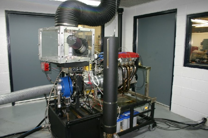
The air is ducted from the filter box via 18” diameter stainless tubing through two axial-flow fans that allow me to adjust barometric pressure of the plenum atop the room. Air exits the plenum through straightening vanes into the Superflow air flow transducer. From there, the air travels through 12” flex line to the plenum box where the engine’s intake duct or air cleaner is located. We built a number of these plenums so we can accurately measure airflow through virtually any intake system the engine may use, including individual throttle bodies. Some of these plenums are dyno mounted while others are floor standing. See below.

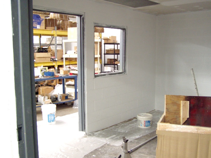
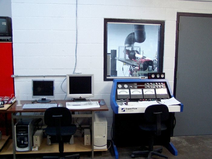
Each of the viewing windows consist of dual panes of ¾” Margard Lexan, which are sealed with silicon and mechanically held in place by steel rails at on all sides. I left a couple small breathing spaces between the inner and outer panes to prevent possible fogging should there be significant temperature differentials between the inside and outside of the room. We use the two windows for better monitoring of the clear oil lines we use for breather tank connection. Our engine customers also like the additional viewing area the two windows afford.
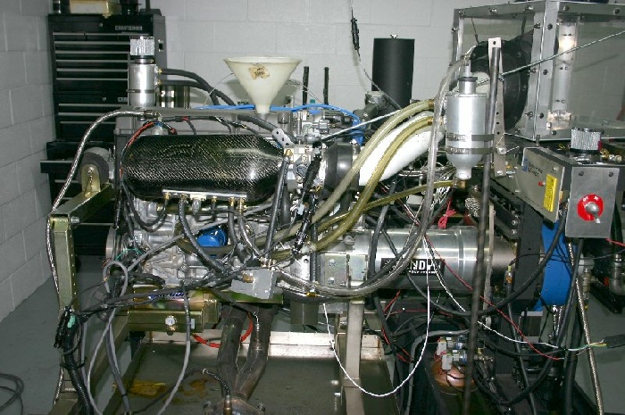
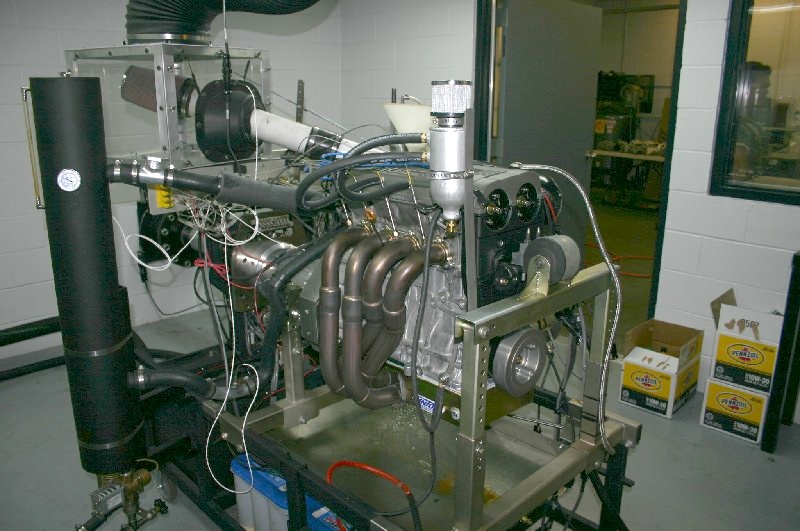
I don't like all the wiring for these engines like most of you, and I can assure you that while building the harnesses I longed for the days where there were only two or three wires required for engine "connection", but we can pull the engine and replace with ease in 15 minutes, so we really have very little down time. Had we not spent all the time building everything for quick and sure connection.....I'd have to look at all this as work rather than the hobby I enjoy so much. .......and before you ask, I do use Pennzoil for quick ring seating on these Honda's.

Along with heavy-duty door seals, we used a piece of
3.5” ID plastic pipe inserted through the wall at floor level for all the
wiring to pass through. I stuff the vacant space with foam runner to give the
room an air tight seal. If I motor the intake dampers closed a bit, it takes two
people to open a door from the inside with the fan running! We've trapped some
friends in the room on occasion using this technique!
That about covers the room’s construction. I attempted to design and finish the room so that any engine adaptation in the future would be as quick and easy as possible. Stopping your dyno tests to work on the dyno room just adds to frustration and ultimately affects not only test quality, but also schedules, so I recommend that, if you’re planning a dyno room, think things through thoroughly and collect all the components you need before beginning the project.
I can also tell you that you'll never get the quality work you're looking for by hiring contractors to do any of the construction...and it's frustrating as hell to have spent money, only to have to tear it apart and do it yourself in the end.
I don't like working on cars, and after this project, I've identified quite a number of other jobs that I wouldn't consider as an occupation in the future.
LW