Current Application (How-To)
The trench chamber discussed is for an "ideal" engine where
anything goes, but many of the efficient burn characteristics can be applied to more
conventional four and two valve heads. In any case, the chamber’s greatest volume
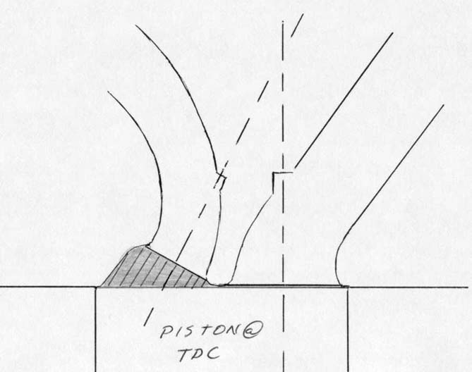
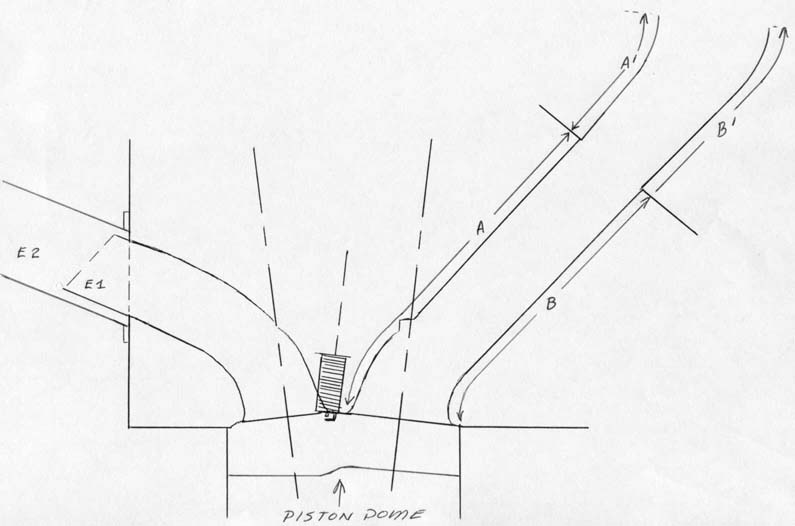
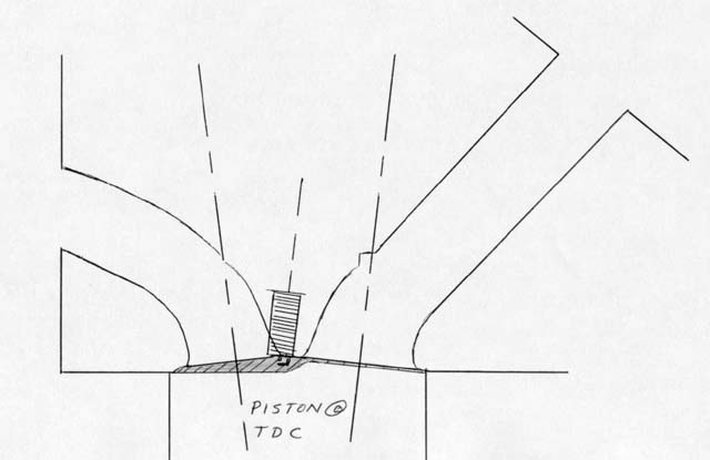
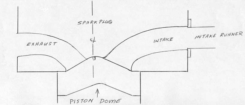
should be around the exhaust valve (with the piston at TDC) and the spark plug should be
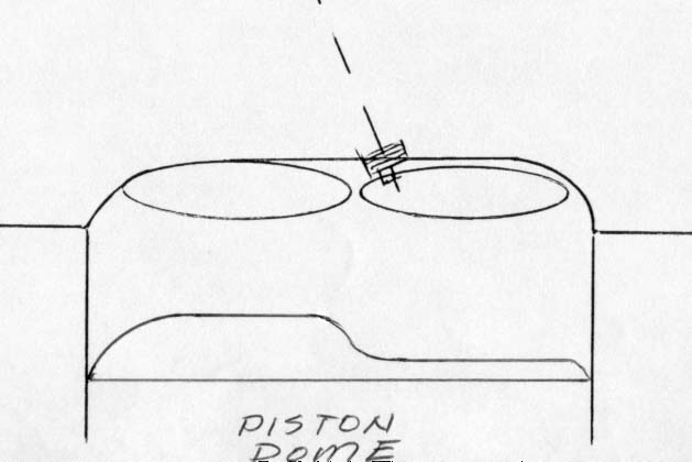
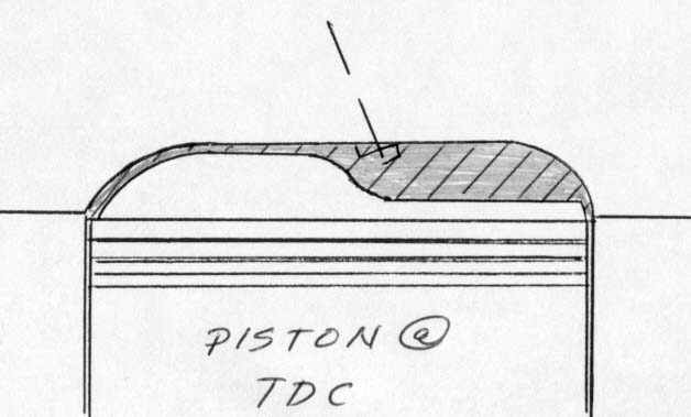
located high and in the same area as the exhaust valve. As the piston top is the floor of
the chamber for a short period of time, it needs to be shaped to displace as much volume
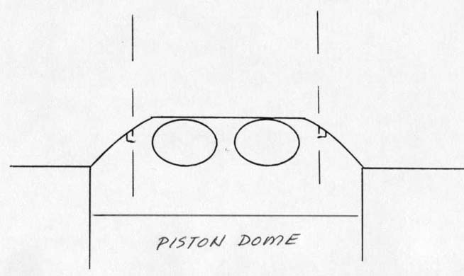
on the intake side as possible. This will generate a piston with a dome on the intake side
and little or none on the exhaust side. The pressure differential created by both the
quench area, and the area displaced by the intake dome will force the mixture to the area
of greatest volume about the exhaust valve(s), where the spark plug(s) reside. In turn, a
very large portion of the mixture will be available in the area where the natural
ionization process begins and subsequent exposure to the initial flame front will
producing a quick and thorough burn for all of the remaining mixture. So we want to
mechanically force the mixture to the exhaust side, ignite, and briefly confine it for
complete combustion.
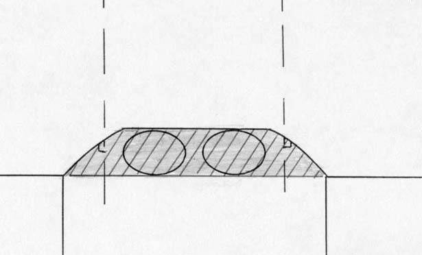
To make this particular concept even more efficient, we can shape the
piston dome and quench pads to force the mixture to swirl into the preferred portion of
the chamber, creating swirl combustion. As the inlet port will induce a swirling mixture
to the cylinder which is rotating due to inertia, the proper piston to chamber shapes can
effectively reaccelerate the swirling charge, while ever confining it to our exhaust side
"sweet spot" for ignition and initial burn propagation. This type of mechanical
enhancement is quite obvious in almost every cylinder head / piston that we develop,
especially when rules confine us to use "production" dimensions.
Less Work = More Power
If the combustion process is quick and complete, there will be very little
burning when the exhaust valve opens, and the exhaust gas temperature will be very low. A
quick burn also permits us to use less ignition timing advance to complete the combustion
cycle and, therefore, the engine is doing less "negative" work since we’re
not trying to compress as much ignited and rapidly expanding mixture. Unfortunately we
can’t light the mixture at TDC and still complete the burn by BDC (with gasoline),
but we can run only 5 - 15 degrees advance and create a thorough burn cycle. Then, by
keeping the exhaust valve shut to a point very near BDC, we can gain a little more work
from precious cylinder pressure. At these crankshaft angles the mechanical
"push" is admittedly small due to the rod angle, but, as we only produce power
on one of four strokes, we opt to take maximum advantage all the pressure available.
Support Systems - Camshaft(s) Configuration
Now we’ll look at some of the support systems, starting with the
camshaft. In order to configure the piston dome so that at TDC, there’s minimal
volume on the intake side, the camshaft must open the valve very little prior to TDC on
the overlap cycle. Once past TDC, the valve may open at the same rate the piston is
traveling down the bore until approximately 12 degrees past TDC, when the piston’s
out of harms way. Once the piston is clear, we "slam" the valve open with as
much velocity as permitted by the mechanical limits of the springs and other related
components. So there are three motions on intake opening: open slow (little or no valve
relief necessary), transition to piston velocity, and then to maximum velocity. On direct
acting overhead cam applications, we frequently open the inlet valve prior to TDC, close
it at piston speed, let it remain on it’s seat at TDC, open at piston speed, and then
smack it wide open. This allows us to get things in motion on the inlet side before TDC,
and it also allows us to keep the valve on its seat at TDC so there are no valve relieves
on the intake side of the piston. As these motions are very complex, we often use several
separate lobes with each doing one particular function and all acting on a single valve
"bucket", or properly radiused rocker arm. Needless to say, in some applications
valve spring life is marginal, but in most applications we’re controlling valve
closure pneumatically, so dependable closure is almost a non-issue
On the exhaust side, everything’s easy. Open the exhaust valve at or
near BDC, allow an efficient (sonic) port to efficiently remove the inert gasses, and then
seat the valve near TDC. Piston to valve clearance isn’t an issue here, as we have
all that "space" over and around the exhaust valve.
The actual length of the cams' events is entirely a function of
maintaining the correct combustion space, while allowing enough fresh mixture in and spent
gasses out, as required by the engines displacement, desired output, and permissible
operating RPM range. This now brings us to the subject of ports.
Port Support -Exhaust Ports
The exhaust port is a proper place to start. For years we’ve tweaked
exhaust seat configurations and used theoretical radiuses to create ports that flow well
without turbulence. In the late '70's we found that if you decreased the cross section of
the exhaust port to the point where the flow exceeded mach 1, the amount of work necessary
to properly scavenge the cylinder was almost nil. By placing the port's smallest cross
section well below the seat insert, the flows maximum velocity was now in an area where we
could control the sonic shock and use it’s placement to allow the port to literally
"pull" the flow out. On the flow bench, these ports tend to become extremely
turbulent and noisy until approximately 7% net lift is obtained and then the port smoothes
out, making a smooth "scream" that certainly requires ear protection. The early
"noise" was created when the flow was in the trans-sonic range, and once past
mach 1, it’s a screamer. To relate to typical exhaust port operation on a flow bench,
one normally needs to adjust the pressure drop with each incremental valve opening to
maintain the correct test pressure. With the sonic configuration, once port velocity is
past mach 1, little or no additional adjustment to the pressure drop is necessary and the
flow rate will continue to increase dramatically with each sequential valve opening. Since
we’re not using additional pressure to increase flow as the valve opens, we have, not
only a very efficient port, but also a port that acts as a vacuum, literally sucking the
exhaust out, and eliminating the pumping losses normally incurred. An additional benefit
is that since the point of maximum velocity is "down in" the port, the seat area
is no longer sensitive at all, and simple three angle seats now flow as well as the
radiused seats previously necessary. Torque is also greatly enhanced by the small area
ports, and the shapes and areas used to control and place the shock wave do not allow the
ports to flow well backwards at all, so there is little inert gas left to contaminate the
fresh intake mixture.
Support Systems -Intake Ports
The intake port: where to begin? These are some design criteria that are
used in all our intake ports.
Start by assuming that the manifold runner is a portion of the port and
the combination is designed to deliver a well-prepared mixture to the port and cylinder.
The entry to the port should always be a tiny bit larger than the manifold exit, and it
should effectively capture the mixture and straighten it so we may manipulate it down
stream. The intake port should never be in line with the cylinder bore axis, or there will
be little quality mixture turbulence, which is a necessity. While on this particular
subject, we do not feel that "tumble" delivers the proper mixture quality
necessary to support efficient combustion, period.
When designing the intake port / manifold runner, the measurement of the
length of the roof should equal the length of the runner and port floor (including the
short turn radius). This provides equal surface friction for the length of the port and
will help keep the mixture intact by reducing the tendency to shear the flow. The texture
of the intake runner and port should be consistently coarse to prevent boundary layer
build up and the resultant tendency to develop surface tension and subsequent fuel
attachment.
The intake port throat should expand in area slightly during the short
turn radius section (regardless of height) to lower velocities and increase pressure
providing the necessary energy to enhance the mixture transition through the seat region
and on into the cylinder. The intake valve seat should be configured using a single
discrete seat angle with the combustion chamber defining the OD and the ID should be
established with a short (.010") 58 degree bottom angle. The configuration of the
remaining lower shapes intersecting the port should be designed to create a longer short
turn "roll" and a steep side and back wall approach to the seat, so the inner
angle blends to shapes which are not concentric with the seat. This is all in an effort to
create equal roof and floor lengths. One added benefit of this seat configuration is that
it does not invite reverse flow, and subsequent power losses.
Support Systems - Port Nitty-Gritty
While we're discussing valve jobs, some additional thoughts need to be
outlined regarding the configuration of valve seats. I consider the valve seat to be the
single most important aspect of intake port preparation. It's absolutely essential that
machining tolerances be held to .0001". The individual valve stems should be
externally honed to a proper finish and each valve guide should be honed to fit the valve
selected. When finished, each valve will have it's own numbered guide. As the tolerances
of the valve to guide clearance will be extremely tight, the run-out tolerance of the seat
should also held to .0001". When preparing to machine valve seats, we place a fixture
on the cam side of the head with springs loading the upper portions seat buckets.
Sparkplugs are torqued in place, and we always use a torque plate / head gasket bolted to
the head's deck. The last bit of effort to simulate the real world is to pump 220 degree
coolant through the water jacketing of the head while all seat machining takes place.
These steps may seem to be excessive, but if they weren't necessary, we wouldn't do them.
All seat machining is also based on centerless-ground pilots which are a "no
taper" fit in each guide. We also feel that all adjustable pilots should be discarded
as trash and any "reputable" machine shop should feel the same way. Now, back to
the port.
The port itself should be configured to work with the chamber and cylinder
wall to create a flow bias that will tend to cause rotation of the mixture in the
cylinder, which we now call swirl. The studies and tests all indicate that it’s
indeed possible to design ports and surrounding areas in the cylinder to allow optimal
swirl frequency at almost all RPM ranges.
How Can It Really Work?
Since the RPM and swirl combination are still thought by many
"experts" to only work at specific and narrow RPM ranges, I need to address this
issue before continuing. Those of you familiar with air flow studies understand both the
elastic and compressible properties of air and you should also understand how air flow is
easily "cheated."
Variable Port Geometry?
One example is the old port designer's tricks with sharp short turn
radiuses, which can cause enough turbulence at their peaks to make the main body of the
flow "think" that the short turn is actually higher with a more optimal
configuration, thus enhancing the flow rates. The ability to separate a small amount of
air from the "bulk" of the flow and use it to "blow" new boundaries is
actually more effective than physical dimension changes to the port. This technology
allows the port shape that the airflow "sees" to actually vary and be
flow-optimized for all RPM ranges.
Jet Fighters vs. Cylinder Heads?
Another "easy to see" example is in the inlet design for many
high performance jet aircraft. Jet engines do not like supersonic flow at the entry or
compressor side. The fix has always been the design and utilization of a variable geometry
inlet, which can open and close the inlet area to keep the airflow agreeable with the
engine. The General Dynamics engineering team changed all that with the F-16 lightweight
multi-role fighter. They engineered a unique under-hanging inlet, which used the airflow
vectored by the front raydome shape to alter the inlet cross section available for the
airflow entry. The faster the airplane went, the less inlet area was presented to the
oncoming air and the engine was happy at both subsonic and supersonic speeds. The fact
that they were able to "cheat" the airflow allowed the airplane to cost less and
also weigh less than the articulated alternative. You can see this same engineering in
both the Boeing and Lockheed Martin JSF designs.
It's All The Same
Applied to inlet ports, we are able to allow the flow velocity to dictate
which portion of the port will influence it into the cylinder. As RPM and velocity
increase, it's relatively easy to design the port to maintain a reasonably constant
frequency and "friendly" bore radius for flow rotation in the cylinder. This
prevents excessive degradation of the swirl/mixture quality at low RPM and it also
prevents the probability of wet-out in the cylinder due to increased rotational velocity
at high RPM. In the case of port modification, it's now possible to design ports that run
well at all RPM ranges, without great tendencies to favor a narrow operating band.
Complex? Not really. It's simply the result of studying all the variables
involved and optimizing each to work in harmony with all the other parts of the engine. My
associates call it the "leave no stone unturned" method and experience has
repeatedly shown that, if we don't look everywhere, someone else will, and they'll kick
our asses.
Cylinder Mixture Composition
All our original data that was made public indicated that we were
achieving a very homogenous mixture in the cylinder with swirl inducing ports. The
increased power and fuel efficiency were simply due to better mixture quality control
prior to ignition and during the "confined" burn on the exhaust side of the
chamber. Our assumptions were only partially correct.
As we were able to more readily study the contents of the cylinder mixture
with more sophisticated equipment, we were amazed to find that the mixture was homogenous,
but also layered as we sampled the cylinder’s entire contents from top to bottom.
These layers are like stacked disks of homogenous air and fuel mixture. The uppermost
layers are of about 12 -1 air/fuel ratio with each lower layer blending to leaner
consecutive layers as we progress to the bottom of the cylinder. The lower layers are
frequently at mixtures of 28-1 or leaner, which can not be ignited by spark ignition.
During the final stages of compression, the upper mixture at 12-1 is easily ignited and,
as the spark plug is physically located high in the combustion chamber, the upper
"rich" layers are the first ignited. The remaining layers of ever-leaner
air/fuel ratios are being pushed upward and they are progressively ignited easily by the
burning upper layers. This means that, were you to simply analyze the overall cylinder
content, the average air/fuel ratio would likely average 18 -1 or lower and keep in mind
that these are not engines destined for economy runs.
Stratified Charge
While we thought we were doing a better job of mixture introduction prior
to ignition, we were actually creating engines with stratified charge combustion
characteristics. If you look back, Honda introduced the concept to production engines by
using a pre-combustion chamber with a tiny intake valve and the spark plug housed in it.
The pre-chamber was linked to the actual combustion chamber by a large hole. The
pre-chamber inhaled a rich air/fuel mixture through the small intake valve, while the main
chamber inhaled a mixture, which was very lean and difficult to light. The spark plug
ignited the rich mixture in the small chamber and the burn spread to the main chamber
where it was capable of creating a very thorough burn, which, at the time, negated the
need for a catalytic converter.
So we came up with a simple (less moving parts) way to achieve stratified
charge combustion that also tended to produce good power, and was also "soft" in
its ability to tolerate extremely variable mixtures and ignition curves without damage
from detonation.
Let It Be
Normally when designing the chamber and piston configuration we never
check the static compression ratio as long as the "combustion space" is
acceptable, regardless of application (normally aspirated or force fed.) We have found
that many of our engine's compression ratios were well over 23-1, and we also learned that
allowing new customers to know those numbers was not always good for business. Monday
mornings are still always fun when we get the call regarding how well the combinations
ran, then we’ll let them to know part of the reason why. Regardless of the weekend
performance, it still scares them to death.
Could It Be?
Some other interesting observations we’ve made during these years of
testing have also lead us to now believe more than ever that the old definition of engines
merely being glorified air pumps is simply not the case. We’ve worked many a program
where we used a record holding engine as a base line. In every instance, when the
"soft" counterpart was tested, we’d gain perhaps only 8-10% more usable
power, but the recovery time and acceleration rates were in a league all their own. As one
would expect, the specific fuel consumption was always lower, but in every case the
specific airflow requirement for the engine dropped considerably as well. So, now
we’re making more power with the same displacement at the same or hopefully lower rpm
ranges, and the engine’s consuming both less air and fuel. This not only verifies the
fact that we’re achieving greater combustion efficiency, but the airflow relative to
power notions that most believe in are no longer applicable.
Winning Dyno Races
Another brief note: Horsepower and torque numbers from dyno testing are
next to useless in our opinion. We have NEVER had an engine that produced big dyno power
numbers dominate competition. The only numbers we pay attention to are those that relate
to recovery and acceleration capabilities. Horsepower is only a bragging number and it's
really only applicable to steady-state engine operation. The engines we design and produce
are only running steady-state when idling or following the pace car. Nuff said.
Coming To Your Car Dealer Soon!
At the current rate of combustion technology development, combined with
many new low-friction and reflective materials we can now use for construction, I firmly
believe that, with the exception of the exhaust gas temperatures, adiabatic engines with
no cooling systems and regenerative cylinder walls are close at hand. You’re also
going to see some engines running fuels that are also "free" shortly. These are
exciting times, indeed.
One Last Spin
This pretty well brings the "soft head" up to date and the
proper emphasis has been placed where it belongs. As for who runs swirl technology these
days….that's a good question. Swirl is swirl, right?, and it seems that every now and
then someone who has "credibility" mentions it relative to their programs.
It’s also a key marketing tool for people who produce everything from bogus fixed
blades you set on top of your carburetors to cylinder heads, which is where it all began.
I suspect that this update may create another controversy like the first
edition did back in ’85. Both the industry and Endyn have profited from
our controversial programs and, if another controversy is necessary to inspire
"engine people" to look in some new directions, I've done my job well, even if I
get stoned by the "experts" again.
I once again thank Al Kirschenbaum for his comments. I'm not sure that I'd
have written a revision had it not been for his article.
I also want thank my mentor for making me read all the books, which forced
me to build all of my own equipment and to follow the test data they produced rather than
the "mainstream."
Larry Widmer
September 1999
Below are additional drawings to show various
different soft head implementations: