B-16 Cylinder Head Mods (Part II)
Here's the promised continuation. These views are all of a
finished customer B-16 cylinder head. The intended use is normally aspirated, i.e..
high compression with a bottle feeding it at the drag strip. The engine is a
.020" over B-16 in a late model Si. We are also responsible for the
pistons.
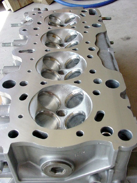
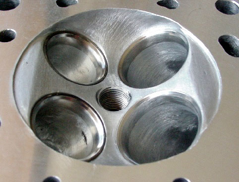
Here's an overall view of the deck surface and combustion
chambers on this B-16 head. Note that all water passages and sharp edges have
been thoroughly deburred.
You may be able to see that the left hand combustion
chamber had some debris venture through at some time in its past. We were able
to fix most of the "tics" and replace the left intake seat to restore
the chamber to optimum configuration. Note that we mill the quench areas (intake
and exhaust) to specific depths to mate with the corresponding surfaces on our
pistons for maximum defined turbulence during combustion.
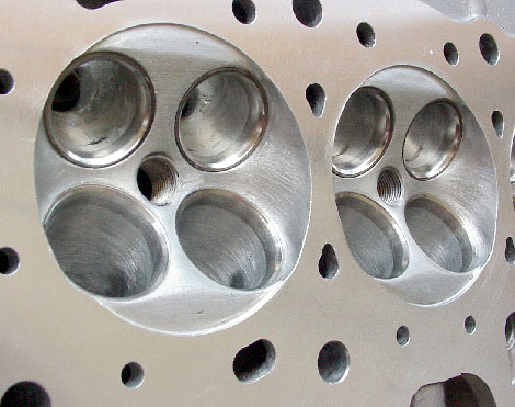
This is a good view of the finished chamber, as well as the
finished intake ports. Note that the valve seats are of a single angle variety,
with the lower approach a blended extension of the port, rather than a series of
stepped discrete angles. The radius of the lower portion of the intake seats
varies from the short turn around to the long wall to effectively equalize the
overall port lengths. Note that the exhaust seats consist of a blended short top
angle transitioning to the actual seat, blending into a radius. This type of
seat configuration is essential, if high flow rates are to be achieved on this
side of the engine.
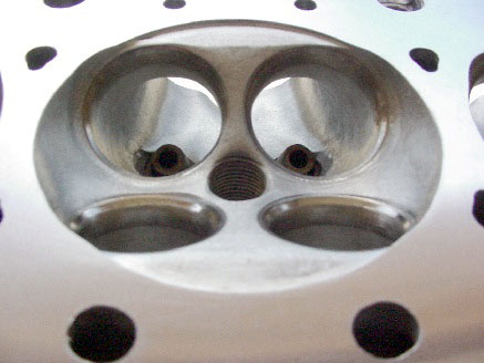
Here's a similar view from the opposite side of the head.
The radius on the exhaust seat configuration is easily seen, with bowl and guide
preparation visible as well. Note the single angle intake seats with the chamber
as the top and OD defining "angle".
One more view of the chamber and the transition from the
ports to the cylinder .....the all important valve seats. This view also
shows the port texture on the intake side pretty well. As you can see, it's not
smooth. You can also see where the texture has been "altered" to
energize the flow a bit on each side of the intake bowls, beginning
approximately .85" below the seats. Notice the texturizing in the sides of
the chambers between the intake and exhaust valve seats. More mixture
conditioning.
Now, I'm following up with some "what happened"
photos. As most of you know, I'm pretty well handicapped, when it comes to all
this web site stuff. For the life of us here, nobody can figure out what went
screwy with the camera, but these strange photos, do show some detail that might
not be so evident otherwise.
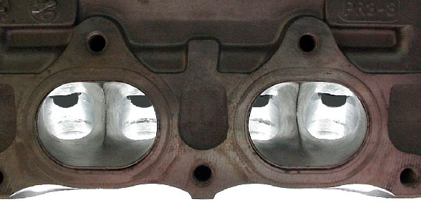
We've been accused of using sorcery in our work by
competitors for years, and perhaps the camera caught us this time. Things of
note are the symmetry of each bowl, the blended seats, and the width of the
"blunt" divider. We keep this wide and softly radiused because it
reduces the tendency for turbulency that's often associated with sharp dividers.
Remember, the leading edges of airfoils aren't sharp.
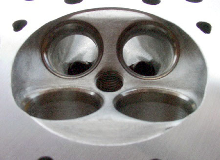
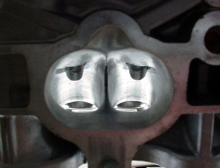
No... we didn't use an arc-light. This particular head is
assembled and gone, so these pics will have to do. These are the two center
exhaust ports. While I tried to center the camera, it's a little off to the
left. It should be pretty evident that the two valves in each port have
radically different bowl and short turn radius configurations. Remember that the
ports are directional on these Honda heads, so one's a left-hander and the other
is a right hand port. Note that the divider is brought to a dull edge. The fact
that the port exits are still smaller than the original gasket (header flange)
size is also of great importance.
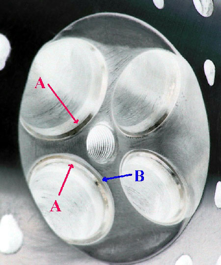
The
intake valve seats are in the upper portion of the chamber. Note that (A) shows
the single discrete seat angle. It's topped by the chamber and followed up on
the downside by the variable radius blend into the port. Also see regular
and inverted versions of this picture side by side.
(A) also shows the single discrete exhaust seat angle. Note
that it disappears in the blend that forms the radius, transitioning into the
port. This picture also shows the upper discrete angle (B) that defines the OD
of the seat as well as setting up the flow. This discrete top angle blends
smoothly into the combustion chamber.
That about sums it up on this installment of the B-16
cylinder head mods. We'll be showing other Honda heads during and after
modification, as we're able. While it's nice to be able to read about porting details,
but a picture's worth a lot more than a thousand words when it comes to this
stuff.
As, I stated earlier....when porting a head, you must be
able to "see" the shapes you're planning to create. The most important
areas to work for flow are all in the valve seat area. You can make damned near
any port flow 90-95% of a fully worked configuration, by doing only the chamber, the
seats and 3/4" into the ports. The ports' entries and exits may be the easiest stuff
to reach and slick-up, but those parts really don't mean anything when it comes to
flow.
Take your time when porting, never get in a hurry and don't
destroy the curves of the short turn radiuses. Contrary to what might
"seem" to be a more direct path for the flow, you have to maintain
large radiuses, or the flow can't negotiate the turns.
Happy grinding!
|