B-16 Cylinder Head Mods (Part I)
This is an semi-complete view of cylinder head modifications
for the B-16 Honda engines. It's meant to be a guide of sorts to some of the
folks who have decided to do the porting modifications themselves.
First, I need to say that the B-16 cylinder head is a
pretty good piece from the factory. The port volume is generous right out of
the box, and unless the head's intended for some very "special" use,
enlarging the ports isn't recommended.
There seems to be considerable core shift in all the
castings we've worked with, so there's a good chance that doing your porting
correctly will mean that the porting won't necessarily be cosmetically
beautiful, so don't count on seeing shiny surfaces everywhere.
I'm starting out with a picture of "Old Trusty"
and the bits that are used for the B-16 job.
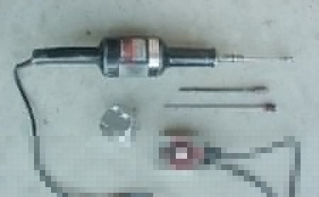
I've inserted a D16 piston to provide a point of reference
in this photo. Note that the grinder is not small. The reason is simple:
It's darned near impossible to properly control a die grinder properly without
leverage. With one hand on the snout and the other on the handle, it's possible
to maintain enough mechanical advantage over the cutter (or polisher) to impart
the shapes you desire. You can't port cylinder heads without your every move being
deliberate and precise.
Note the speed control for rpm reduction. Most pros run the
speed as low as the control will permit. These Dumore grinders will go pretty
darned slow and still provide sufficient torque for the job. Under the handle is
a trigger that is also used as a throttle (or another rpm control). You learn
quickly to regulate rpm and cutter speed by continuously switching the grinders
off and on. The switches do require replacement after every 20 sets of heads,
but they're more than worth the price.
Note that the cutter in the picture is a .5" diameter
oval shaped "alumicut" with coarse (very few) cutting edges. These
cutters are capable of removing material pretty quickly and they also leave a
descent finish that's easily polished to texture. The cartridge roll is a 60
grit .5" long by 1.5" length. Note the rounded nose on the roll. We
shape the square noses by working the cartridge rolls on cinder blocks next to
the grinding benches. A couple seconds will shape a new roll to
"perfection". The split rod has 40 grit paper attached. This works
good on intake ports, while 80 grit does a good job for chambers and exhaust
ports.
I suspect that the length of the shanks on the various
tools might have attracted some attention. It should, because the length is the
key to doing good porting. It's a necessity to stay far enough away from the
work to see what's going on and that's impossible when the cutters have a
3" shank. Every tool we use on cylinder heads is long for this reason and
the additional reach also allows one to complete grinding a radius that's
"hidden" over the crest in the ports. This way, you're not working from
two different directions, attempting to connect two radii at the crest, which
is inevitably the most critical part of the port. Now that you see the length of
these particular tools, the necessity for low rpm operation should be apparent,
since high rpm can make the shanks "whip" and cause major damage.
Now, I have some pictures of some B-16 exhaust ports to
show what you start with and what you'll want to see when the grinding's
finished.
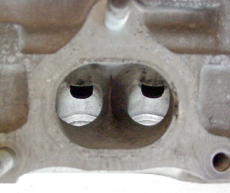
This is the exit view of a stock B-16 exhaust port. Note
that the divider isn't centered in the port. This particular port is #2 and it
angles to the right (if you're looking at the head in plan view with the intakes
nearest for reference). The port should not be reworked to remove the
angle. The crests of the short turn radius are reasonably high (good) and the
shape is ovaled, which is good for low lift flow and great for moderate street
performance. Also note the reasonably deep indentions on the long side of the
bowls at the casting's parting lines.
This is a picture of the same cylinder number's exhaust
port which has been roughed out.
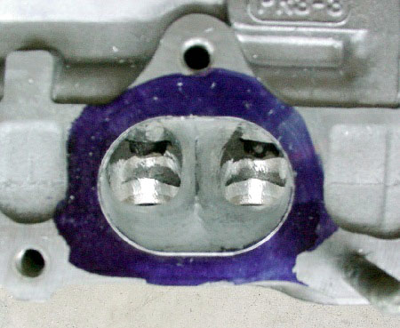
Note that the port exit has remained untouched
dimensionally and center divider is still offset. The floor of the short turn
radius is maintained at the maximum height, but the corners have been widened to
promote greater flow in the mid lift and high lift ranges. These ports will be
at home all the way from low rpm to extremely high revs. It should be evident
that there's an area in the bowls that isn't touched by the grinder in this
picture. When flow patterns dictate that there should be no material removal,
don't screw with it, or you'll degrade the port's performance potential. Pretty doesn't
mean beans to flow (or your engine), so do not get off on some kick where
you think that every part of a port needs attention...it doesn't work that way. The upper
portions of the ports around the sides and rear of the valve guides is area, where the factory dimensions are more than
adequate.
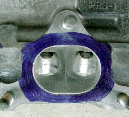
Here's a picture of the same number port that's been
finished. The camera angle is off to the left a bit, so don't be misled. The
divider still has the offset and the features shown in the previous picture are
still there. Note that there are still areas that haven't fallen prey to the
grinder. See stock vs.
finished exhaust port side by side.
This might come as a shock to many of you, but this
particular port would never run on one of our personal engines. It's not due to
any deficiencies, it's due to the finish. A port finished like the one in the
previous shot will perform just as well as this "cosmetically" nicer
port, and since performance is king around here, we'd do the final sizing with
the carbide finish for our own stuff. If it's our own, we don't need to bother
with other's preconceived notions about "looks", so we don't bother.
This particular head is for a customer and we feel somewhat bound to make the
appearances "acceptable", so nobody will make any cracks about
"unfinished" ports.
I need to point out that one of the most important aspects
to properly porting heads is understanding the entire grinding procedure. It's
absolutely essential that the porter know when to end each grinding operation and begin
the next level of finish. If you carbide too far, then any subsequent work with
a cartridge roll will remove too much material and kill the shape and the flow.
Again, going for the looks can really be costly, so it pays to think each
operation through thoroughly.
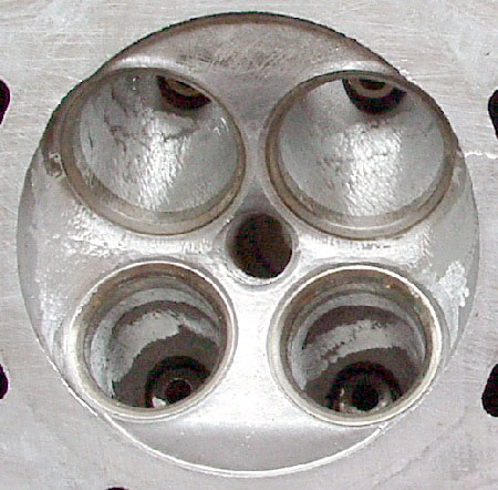
The following picture is of a stock B-16 combustion
chamber, viewing out the exhaust port.
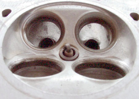
Noteworthy in this picture are the oval shaped short turn
radiuses in the bowls of the exhaust port. Also, some of the casting to
machining irregularities in the combustion chamber are evident.
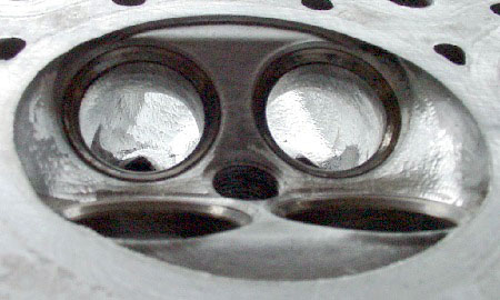
Unfortunately, the camera angle is "slightly"
different in this photo, but the area opened up by grinding the corners of the
short turn radius is pretty visible. Note that some minor carbide grinding has
been done in the chamber as well.
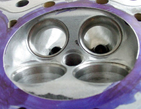
Please forgive the inconsistent camera angle, but here's
the head with the customer exhaust ports. The chambers haven't been addressed on
this casting yet, so you're not looking at some Endyn combustion chamber tricks
here. See stock vs.
finished exhaust port (looking out from chambers) side by side.
Viewing through the exhaust port, it's easy to see the
additional area to the sides that's gained by widening the floor at the short
turn radius of each bowl. A discerning eye might also see the amount of radius
that's been ground into the exhaust port valve seats, in anticipation of the
upcoming valve job. The intake port's seats have also been transitioned from the
bowls with only the 45 degree seat surface remaining. It's obvious that, whoever
did this work either knew what seat configuration was on tap, or he was a
wise-ass....or both!
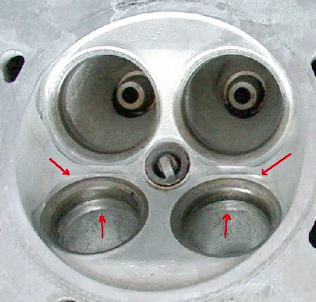
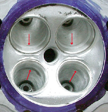
Here's another view of a stock B-16 combustion chamber. The
arrows simply point out the principal areas where the casting and machining
operations meet. In the combustion chamber, blending these ridges will help
maintain mixture homogeneity, flow, and combustion travel.
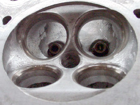
Here's a similar view of another head that's been roughed
out with a carbide cutter. Note that the transition areas in the combustion
chamber have been smoothed and the casting shift in the chambers has been
minimized. The intake ports have been roughed into the proper shapes and the
"no-grind" areas in the exhaust ports are again evident.
It should be pointed out that heads vary from casting to
casting. In this view of the customer head, the exhaust port "underhangs"
are visible, as are the slight indentions beneath the valve seats in the intake
port bowls. While it may be tempting to do that last little swipe with a
cartridge roll to eliminate the "flaws", don't do it. I need to point
out that areas like these are frequently different from port to port in the same
head, so don't be fooled. The amount of shift can frequently grow, as you move
from one end of the head to another. Careful visual inspection can catch these
abnormalities, so you can adjust the grinding from port to port and minimize the
irregularities.
Here's a view from the chamber into the intake ports. This
head is in the process of being roughed out. Note that the grinding in the
intake ports began with the inside of the valve seat inserts and has progressed
into the port bowls. I realize it's hard to see, but the short turn radius has
been properly contoured as well.
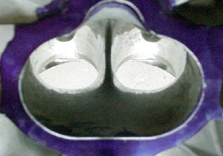
Here's the same intake port. Note that the grinding has
completely developed the shape of the individual bowls, but it's also shaped the
complete short turn radius. All of this shaping has been
accomplished from the combustion chamber side of the head. It's impossible to
rework such critical areas of the intake ports without looking at it from the
flow's point of view in the chamber.
This article will be continued... see Part
II
|